Introduction:
Have you ever looked at the construction of a tube light? You might have noticed the electronic ballast/choke. You might also have noticed how the use of electrical chokes has slowly faded away. We’ll discuss both of them and learn why their use has become outdated.
First we will discuss the basic structure and working of a tube light.
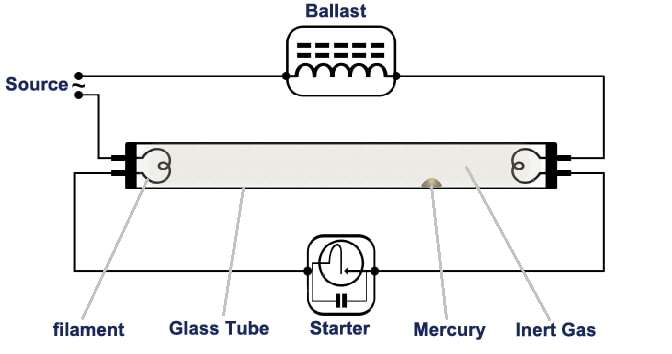
Parts of a Tube Light:
A tube light consists of the following:
- Ballast
- Tube light starter
- Switch
- Discharge tube
Working of a Tube Light
Contents
- 1 Working of a Tube Light
- 2 Magnetic Ballast:
- 3 Working of Magnetic Ballast:
- 4 Why are magnetic ballasts being replaced?
- 5 Electronic Ballast:
- 6 Working of Electronic Ballast:
- 7 Difference between Electronic Ballast and Magnetic Ballast: Electronic ballasts change the frequency of the current without any change in the voltage. Magnetic ballasts work at a frequency of around 60 Hz, whereas electronic ballasts work at an increased frequency of around 20,000 Hz. This is why fluorescent lamps using electronic ballasts do not flicker or emit any buzzing sounds.
- Initially, the switch of ON, the tube light will experience full voltage through the ballast and fluorescent lamp starter and no discharge will occur i.e. no output from the lamp.
- A glow discharge will be established in the starter due to maximum voltage and the bio metallic strip will melt and conduction will begin.
- The gas in the starter ionizes and then due to full voltage it heats the bio metallic strip which bends and connects to the fixed contact. As a result, a large current flows through the starter.
- The voltage will gradually decrease due to the current and the current flows through the tube as the tube light as a lower resistance as compared to that of the starter.
- The discharge of mercury atoms ultraviolet radiation which excites the phosphor powder coating to radiate visible light. Actually, the tube light does not contain the glowing filament of an incandescent bulb but instead contains a mercury vapor which gives off an ultraviolet light when ionized.
- At this stage the starter gets inactive i.e. during the operation of the tube light.
- Keep in mind that starter is only used in the electrical ballast type not the electronic type of tube light.
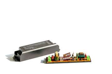
Magnetic Ballast:
Magnetic ballast is actually an inductive coil. It actually looks like a transformer, a copper wire wound over a core material. Inductors are generally used to oppose a change in current passing through them.
Working of Magnetic Ballast:
- In order for the tube light to work, the electrodes must be at a high temperature.
- Initially, the ballast will oppose the current as it first goes straight into the starter and so prevents any damage.
- The starter is in series with the ballast and works as a switch. After the current exceeds the rated value, the starter material melts and forms an open circuit.
- Thus, the current passes through the tube light. The high current produced for the discharge is created by the opposing current which is stored in the inductor, hence the circuit lights up.
- As air medium is present, the current through it ionizes and resistance decreases progressively. Resultantly, the current starts increasing.
- The inductance coil will now act as a reactive load which limits the current.
Why are magnetic ballasts being replaced?
Now, magnetic ballasts are being replaced by the electronic versions as they are not as sophisticated and have higher drawbacks. Magnetic ballasts are used in light sockets i.e. between the plug for the light bulb and power cord.
The current in magnetic ballasts flows through the copper coils before moving on to the light bulb. Most current gets caught in the magnetic field generated and only a small amount of current is transferred to the light bulb. The current that passes through depends on the thickness and length of the copper coil. Due to the inconsistent flow of current through the light bulb it flickers and also creates that buzzing sound you might have often heard.
Electronic Ballast:
Electronic ballast controls the starting voltage and the operating currents of lighting devices. Electronic ballast usually operates with our A.C source of 220V, 50-60 Hz Frequency. The electronic ballast consists of a rectifier which converts the A.C input into D.C. output. The D.C. current thus obtained is filtered by capacitors. This filtered current is then passes through a series of induction coils and fed to a high frequency oscillator. Hence, the output current is at a very high frequency (around 20-80 kHz).
Working of Electronic Ballast:
After the D.C voltage is filtered it is passed through the high frequency coils. Here the oscillation depends on the input voltage and frequency. A small amount of inductance can be considered here, which is associated with the high rate of change of current and high frequency. The inductance can be represented as: I=L(dI/dT).
Around more than 440 V is required for the lamp to glow. Once the switch is turned on, the lamp experiences a voltage of around 1000 V, so gas discharge take places instantly. Once discharge process is started, the voltage across the lamp will decrease below 230-125 V. Then, the electronic ballast allows limited current to flow through the lamp and prevent any chances of short circuiting. The electronic ballast acts as a dimmer while the fluorescent lamp is running so as to limit the current and voltage
The electronic ballast does not produce substantial amounts of fundamental reactive power. However, it allows for higher efficiency by saving energy. They feed lesser power into the lamp as compared to magnetic ballast. However, they are much more expensive and are more prone to certain types of damage.
In this device an EMI filter is used to block any electromagnetic interference, a rectifier is used to convert A.C. to D.C. and a half bridge resonant converter is used to convert the D.C to a square waved voltage with high frequency.
Difference between Electronic Ballast and Magnetic Ballast:
Electronic ballasts change the frequency of the current without any change in the voltage. Magnetic ballasts work at a frequency of around 60 Hz, whereas electronic ballasts work at an increased frequency of around 20,000 Hz. This is why fluorescent lamps using electronic ballasts do not flicker or emit any buzzing sounds.
Electronic ballasts are also quite smaller in size and weight. They are much more energy efficient as compared to magnetic ballasts.
Electronic ballasts can be used for lamps that are connected in parallel or series. In this case, if any single lamp goes out, it will not affect the performance of other lamps using the same ballast.