Arduino Based MPPT Charge Controller | Alternative energy |renewable energy sources | clean energy
Contents
- 1 Arduino Based MPPT Charge Controller | Alternative energy |renewable energy sources | clean energy
- 2 Abstract
- 3 How MPPT works? Why 150W solar panel does not equal to 150 w?
- 4 Specification of the project
- 5 Electrical specifications:
- 6 PARTS REQUIRED:
- 7 Libraries Required For Arduino IDE :
- 8 Model of Arduino Based MPPT Algorithm Charge Controller | Alternative energy
- 9 Project Flow Chart :
- 10 Project Simulation in Proteus by Using Arduino Nano ( UPDATED 2019)
- 11 WiFi Data Logging by using a Wifi module ESP8266
Abstract
For maximizing a photovoltaic (PV) power, continuously tracking the maximum power point (MPP) of the system is highly required. MPP of the PV system depends on solar radiation conditions, ambient temperature, and the load demand. Maximum power point tracking (MPPT) techniques can catch MPP of PV system. Such techniques can be realized in many various forms of hardware and software. The goal of this project was to develop, construct, and test a working solution to the MPP problem with a limited budget. This tutorial Contains the general circuit of MPPT, the panel cell and it is a formula, about how MPPT works, the required parts and sub-circuit. we choose buck converter in our project and explained how to use Arduino and how to apply it in Proteus.
What is Mppt ( Maximum power point tracking)?
We use MPPT algorithm to Extract the maximum available power from the Photovoltaic module under certain conditions. MPPT is a Most Popular tool that helps us to use Solar Energy (Renewable Energy Source) in an efficient way. If we want to Reduce the Graph of Carbon footprints then we must need to move towards clean Energy which is called Renewable Energy ( Energy we can get from Natural resources) Like SOLAR, HYDRO, WIND e.t.c otherwise we will directly move toward Global Warming. Every Country needs to Move towards the Green Energy especially CHINA because it is the Main contributor by producing 63% Co2 | Alternative energy.
How MPPT works? Why 150W solar panel does not equal to 150 w?
For example, you bought a new solar panel from the market which can deliver 7 amps current, under charge the setting of a battery is configured to 12 volts: 7 amps times 12 volts = 84w (P=V*I) You lost over 66 watts – but you paid for 150 watts. That 66 watt is not going anywhere, but it,s due to the poor match of the solar output current and battery voltage.
After using MPPT algorithm we can get the Maximum available power Battery gets is now 12 amps at 12 volts Output power is equal to p= V*I p=12*12=144w Now you still have almost 144 watts, and everyone is happy.
Specification of the project
1. This project is Based on MPPT (Maximum power point tracker) algorithm
2. LED indication to show the low mid and high level of charge stat
3. LCD (20×4 character ) display for displaying power,current,voltages etc
4. Lightning /Overvoltage Protection
5. Protection For Reverse power flow
6. Overload & Short Circuit Protection
7. Logging data through WiFi
8.Charge your Cellphone, tablets any gadgets through USB port
Electrical specifications:
1.Rated Voltage= 12V
2.Maximum input current = 5A
3.Load current support up to =10A
4. Input Voltage = Solar panel 12 to 24V
5.power of Solar panel = 50 Watts
PARTS REQUIRED:
- Resistors ( 3 x 200R ,3 x330R,1 x 1K, 2 x 10K, 2 x 20K, 2x 100k, 1x 470K )
- TVS diode ( 2x P6KE36CA )
- Arduino Nano
- ( ACS712-5A ) Current Sensor
- Buck Converter ( LM2596 )
- Wifi Module ( ESP8266 )
- LCD display ( 20×4 I2C )
- MOSFETs ( 4x IRFZ44N )
- MOSFET driver ( IR2104 )
- 3.3V Linear regulator ( AMS 1117 )
- Transistor ( 2N2222 )
- Diodes ( 2x IN4148 , 1 x UF4007 )
- Capacitors ( 4 x 0.1 uF, 3 x 10uF ,1 x100 uF ,1x 220uF)
- Inductor ( 1x 33uH -5A )
- LEDs ( Red, Yellow, Green )
- Fuses ( 5A)
Libraries Required For Arduino IDE :
- TimerOne.h – Click Here To Download This Library
- LiquidCrystal_I2C – Click Here To Download This Library
Remember: Make a New Folder ( Folder name should be same as library names like TimerOne and LiquidCrystal_I2C. Paste these Two Folders in Arduino/LIbrary.
Model of Arduino Based MPPT Algorithm Charge Controller | Alternative energy
Project Flow Chart :
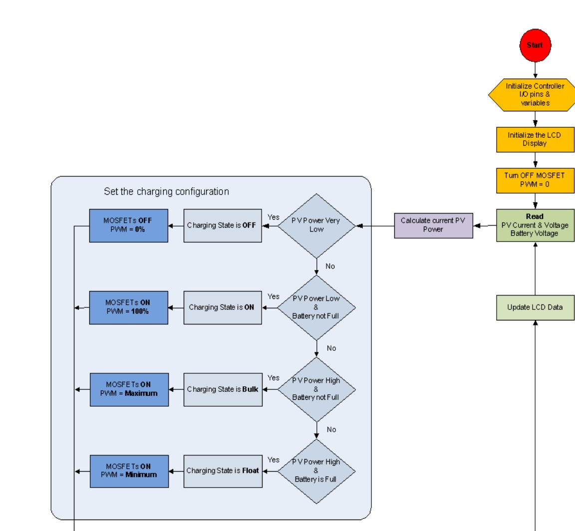
Starts reading its analog inputs:
- The voltage supplied by the PV panel
- The current drawn by the PV panel
- The voltage of the battery
Once all inputs are read, it calculates the current power supplied by the PV panel by multiplying read voltage by reading current.
Then the charging configuration is set according to the above readings:
- If the supplied PV power is very low (night time, cloudy weather, dirty panels) the charging state is set to OFF, The MOSFET driver is shut down, and the PWM rate is set to 0%
- If the supplied PV power is low and the battery is not fully charged, the charging state is set to ON, the MOSFET driver is enabled, and the PWM rate is set to 100%.
- If the supplied PV power is medium to high, and the battery level is not fully charged, the charging state is set to Bulk, the MOSFET driver is enabled, and the PWM rate is set to 100%.
- If the supplied PV power is medium to high, and the battery level is fully charged, the charging state is set to Float, the MOSFET driver is enabled, and the PWM rate is set to Maximum.
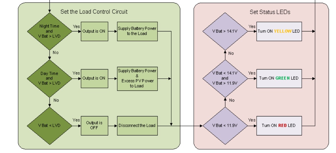
The next task is the settings of the output load control:
- If it is night time and the battery voltage level is higher than the “Low Voltage Disconnect” threshold which is 11.9V, the output is enabled and the battery supplies its energy to the load.
- If it is day time and the battery voltage level is higher than the “Low Voltage Disconnect” threshold which is 11.9V, the output is also enabled, but this time the load is energized by the battery and by the excess energy supplied by the PV Panel
- If the battery voltage level gets below the “Low Voltage Disconnect” threshold which is 11.9V, the output gets disabled and the load gets disconnected.
The next step is to set the Battery voltage indicators by turning on the corresponding LED:
- If the battery voltage level is lower than 11.9V, then the RED Led is turned on.
- If the battery voltage level is higher than 11.9V but lower than 14.1V, then the GREEN Led is turned on.
- If the battery voltage level is higher than 14.1V, then the YELLOW Led is turned on.
Next, the Arduino updates the information displayed on the LCD screen according to the above processes and then starts another reading of the inputs to start the loop phase process once again, and then it continuously repeats this loop over and over.
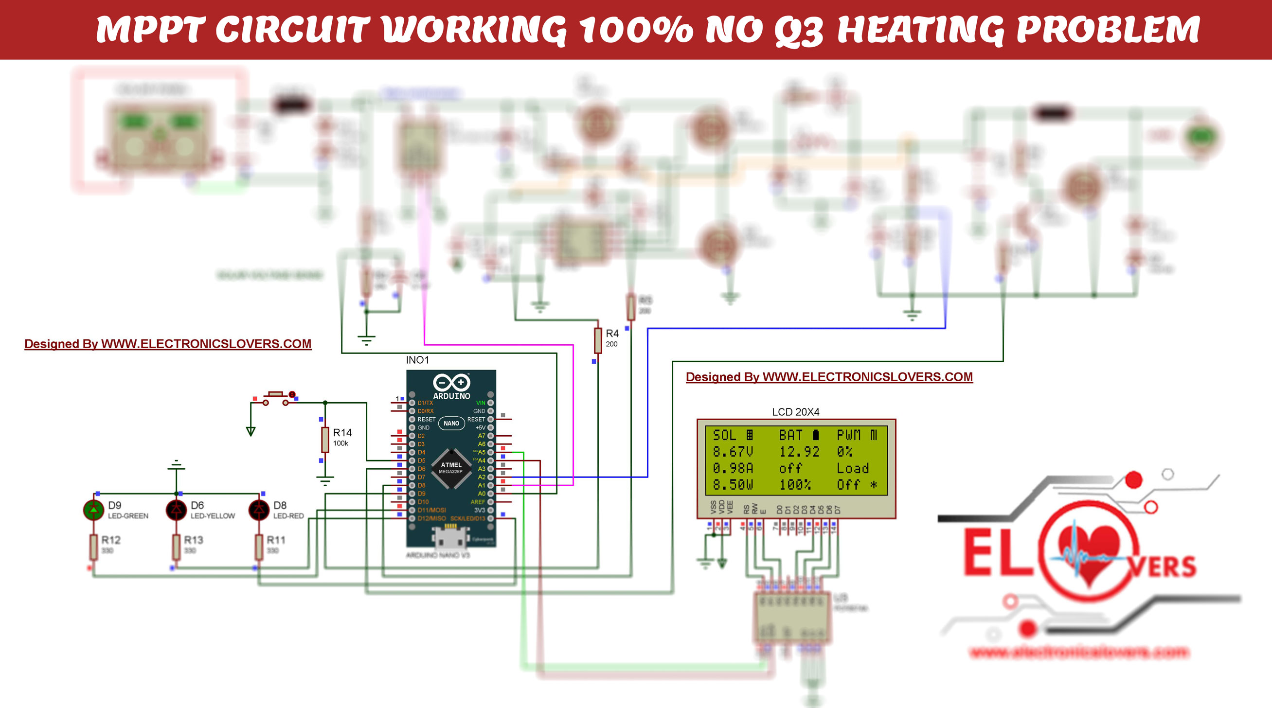
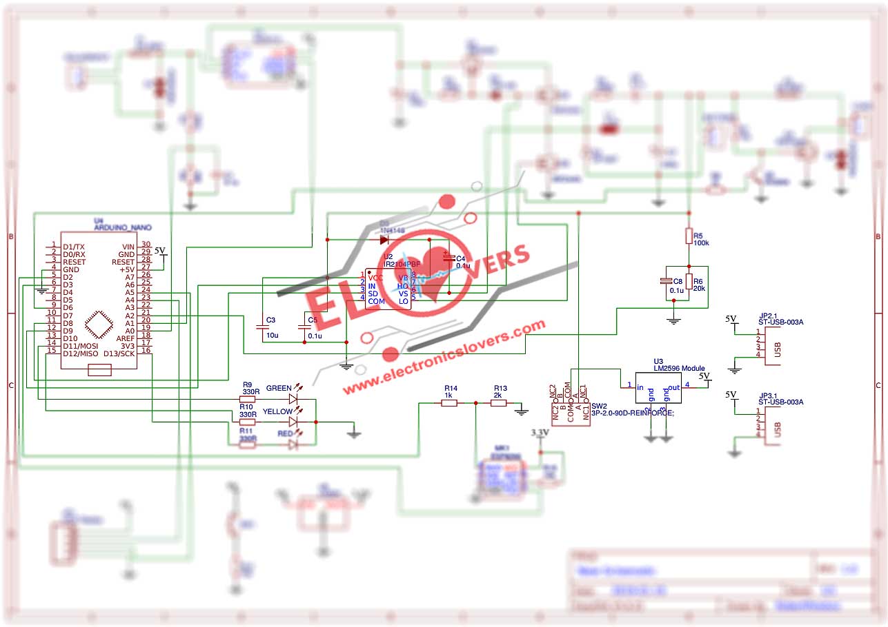
Project Simulation in Proteus by Using Arduino Nano ( UPDATED 2019)
Section A: is the input of the system which is the power supplied by the solar panel. The fuse F1 and TVSs represent the protection network against any high current that could happen to the circuit. The Voltage divider network (R1, and R2) are used to scale down the voltage provided by the solar panel (VPV) so that the maximum voltage supplied to the Arduino analog input (A0) doesn’t exceed it the maximum voltage limit which is 5V. The output voltage of the voltage divides is one-sixth (16) of the input voltage. So the maximum value for the PV panel voltage should not exceed 30V.
VA0= R2R1+R2 VPV= 20100+20 VPV= 20120 VPV= 16 VPV
Section B: is the current sensing network for the power supplied by the PV panel. The ACS712-5 is a hall-effect current sensor chip whose output is an analog signal proportional to the current passing through the chip. The capacitor is a general filter capacitor. The output of the current sensor is connected to the second analog pin of the Arduino (A1).
Section C: represent a blocking circuit that allows the current to flow in only one direction which is from the PV panel to the charging circuit. The aim of this circuit is to protect the PV panel from the battery voltage when the solar panel is not producing electricity. The MOSFET transistor Q1 gate pin is connected to the MOSFET driver chip (IR2104) through the diode D3. So that Q1 is engaged only when the MOSFET transistors are operational.
Section D: is the charging network. The MOSFET driver chip will control the MOSFET pair Q2 and Q3 in a push-pull configuration to enable the current to flow inside the coil. The output of this network is connected to the battery to be charged.
Section E: is another voltage divider connected to the third analog pin (A2) of the Arduino. This network feed the voltage of the battery into the Arduino to measure it.
VA2= R8R7+R8 Vbat= 20100+20 Vbat= 20120 Vbat= 16 Vbat
Section F: is the output load control circuit. The Arduino output pin (D6) control the base of the NPN transistor Q5, which in turns control the gate of the MOSFET transistor Q4
responsible for allowing/ block the current to flow from the battery to the load. Whenever D6 is low (0V), the base of Q5 will be high, and the MOSFET Q4 will be passing the current. When D6 switch its state to High, (5V), the base of Q5 will be High, and the MOSFET Q4 will be open circuit and the current flow will be blocked.
Section G: is the Push-Pull MOSFET network driver. It drives the MOSFET transistors Q2 and Q3 based on the signals generated by the Arduino board at pins D8 and D9.
Section H: is the voltage regulator circuit responsible of supplying the Arduino with the rated voltage (5V). The input to the regulator is the battery. The output of the regulator are mainly the Arduino board and the LCD display.
Section I: is the serial LCD display. It uses the I2C protocol to communicate with the Arduino Board.
Section J: is the visual indication LED used to state the voltage level of the battery. The resistors R11, R12, R13 are current limiting resistors used to prevent the voltage supplied by the Arduino (5V) from damaging the LED which requires only 2 volts to operate.
WiFi Data Logging by using a Wifi module ESP8266
Read This Article: Learn How to Setup the Wifi Module ESP8266 by Using Just Arduino IDE
- Go and Sign Up in https://thingspeak.com/
- Make a New Channel and write “Solar Panel Data” in Field 1 and leave other fields blanks and save it.
- You will Get API key, Copy that Api Key and Paste in Source Code.
- Done
Made by Students from KSA
Click Here To Buy Source Code + Schematic Diagram + Proteus Simulation File (Arduino UNO & Nano) + Complete Project Report (50 pages) From Our Official Online Store | Share your Project Video (HD) with us and GET $10 Cash back
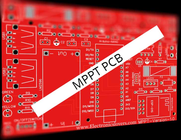
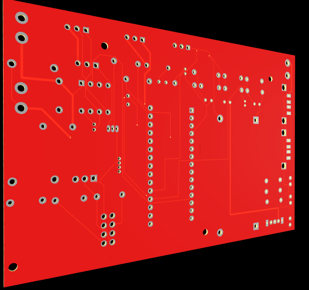
PCB-Board By Electronicslovers ( 31 January 2019)
Contact Us if you are interested to Buy PCB Gerber File
“Do not forget to install all the necessary libraries before uploading the code to Arduino Nano ” If you found any difficulty while making this project so don’t hesitate to ask first we are here to help you 24 hours a day and 7 days a week 24/7 thanks
200 comments
Hi, nice project. There are some solar converters that are buck boost . The boost will increase PV low voltage under low luminosity condition. For example if the solar panel is generating 5V, it could be boosted and deliver some battery charging current
Regards
Problem with boosting voltage because of low light is that there is little to NO power when that happens
Problem with boosting voltage because of low light is that there is little to NO power when that happens
What would be the pitfalls of trying to run multiples of these in parallel. I'm thinking a system with multiple panels/controllers charging a single battery bank. Much like a system with multiple panels and multiple inverters (like the enphase micro-inverter) running in parallel.
Thoughts?
Visit this link here is the clean explanation
http://www.mpptsolar.com/en/solar-panels-in-parallel.html
yes you are right
then difinitley it,s efficiency will be degrade
Nice project! I can't find IR2104 on my market, It can replace with IR2184 or IR2110 (need to modify schematic??)
check out this one in market IRF3205
It mean driver mosfet IR2104, on your project
Nice project!
Can I use another arduino controller like arduino mega2560 instead of arduino Nano?
Nice project!
Can I use another arduino controller like arduino mega2560 inesNice project!
Can I use another arduino controller like arduino mega2560 instead of arfuino Nanoted to arduino Nano?
MY solar pannel is 100Watt rated vtg:-17.5V & rated current :-5.75amp
Hi,
Is it possible to incorporate an external AC charger in case of insufficient sunlight for several days?
plz reply if we use this pannel
yes you can use but would need some modification in source code
Maximum is 50 to 60 watt for higher watts you need to modify the circuitry by just placing more transistor in parallel …dont forget the heat sink,…enjoy
Nice Idea but you need a Relay to cut off Ac charge when it,s sufficient sunlight and vice versa
Yes indeed..When the panel is producing enough current, AC charger will be disconnect and the solar panel will charge a battery.
just transister place in parrallel no other circutiry changes ?
hi.hope you are well.will you please tell me that is it works with boost convertor?will it be efficient system as in low insolation conditions the voltage may be very low.please guide me about this.
hi. i have project i am working on it. it is only about to get the power from solar and then apply MPPT algorithm using Buck. i just want output source with MPPT without battery charging . Is your code helpful for me or i have to apply new code or my case .
regard
no need a change you can use this code
latest one
Hello wanted to ask what they have for a firmare the ESP8266
LCM1602 is not avalible in market so what we use replace of this one
check this one IRF3205
waqas bhai please app apna question sahi bata dae app ka matlab hai k Market main LCD nai mil rahi am i right ???
IR2104 mosfet driver is not available please suggest another device
Try to fing out 20X4 LCD with module attached you can get this LCD from college road rawalpindi
LCD with module is available at "IC MASTER" shop located at college road go there and buy for your self ………other wise you can change the program and connect lcd without module but i would be a little bit difficult.
I want mosfet driver not mosfet
16×2 lcd is avilible on ic master shop not 20×4
This comment has been removed by the author.
Hi
can I use a fixed inductor that is like resistor in shape instead of the toroid? and what is the effect of doing that?, please
salam.sir we are doing it on atemage8 but we are facing difficulty regarding coding.can u provide it.and secondly we need buck boost or only buck converter.plz explain
NO reply on my comment plz reply.salam.sir we are doing it on atemage8 by using perturb and observe method but we are facing difficulty regarding coding.can u provide it.and secondly we need buck boost or only buck converter.plz explain
i have never used atemage8 if you are using so you must need to update each and every Out/in pins declaration in code …. buck boost is best option otherwise you can use Boost also ..
hi, nice project..
from the schematic the buck converter connector output pin is connected at 5V arduino pin. is suppose to be connected there or Vin arduino pin?
Connect to Vin arduino pin ….You need to do a calibration turn on arduino uno properly using this buck converter ….for this read my article How to Turn on Arduino Using Buck Converter
thanks for the clarification. i notice from picture you posted that there is two(2) extra mosfet is being used..can you show the exact circuit.
hi I have flashed to esp8266 aswell as included the relevant libraries in ardduino IDE but getting this message espcom_open failed
Good day I connected the circuit as on the schematic, but when I add the battery to the project, it keep on burning the 3rd MOSFET the one connected to pin 5 of the mosfet driver. any idea on what might be the cause please.
Thank you.
Powering the MOSFET driver IR2104 from battery terminal ( 12V ) instead of solar panel ( earlier ).
If anyone making this controller, make this changes and test it. If you have any test results / suggestions, comments it below.
Salam, please can you give us your email ?
I want build solar inverter mppt charge controller without battery to run load of 200w please give suggestions and circuit
How can we convert this 12v MPPT charge controller to 24v,36v and 48v?
I have a local made MPPT solar charge controller attach with 24v solar panels its working very good since 2 years.
Now i want switch on to 36v / 48v.
waiting for your reply
Regards
how much is the total cost of this project
how much is the total cost of this project?
Update LCD library
hi!! nice project… this line be red at mine…: LiquidCrystal_I2C lcd(0x27, 2, 1, 0, 4, 5, 6, 7, 3, POSITIVE); and i take an error Positive was not declared in this scope
Have you plans to use it with 24V system and more amperes?
Even with the minimum light (i.e. if you cover it with a cloth) the solar panel gives the voltage (i.e. 18V for 12V panel) it designed to deliver. Only the current is almost 0
HELLO sir ,
Please send me your email address . i want to discuss about mppt .
hello sir ,
I want your project schematic . please send it at my email it is very urgently it is my final year project.
ismailpakmemon@gmail.com
Can we read the battery voltage correctly on the screen only if the battery is connected without the solar panel in the circuit
battery 12v 100Ah
Pmax = 140 Watt,
Isc = 8.39 A,
VOC = 22 V
What is all the changes to hardware and software?
battery 12v 100Ah
Pmax = 140 Watt,
Isc = 8.39 A,
VOC = 22 V
What is all the changes to hardware and software?
battery 12v 100Ah
Pmax = 140 Watt,
Isc = 8.39 A,
VOC = 22 V
What is all the changes to hardware and software?
i am having a 500 watts solar panel what changes i have to do to this circuit to suit my panel? aerokalaiselvan@gmail.com
Sir I want to work on different algorithms of MPPT. Comparison of three algorithms. should I use Arduino or Simulink?
hello..my solar panel is of 20w and battery is 12v..what are the modification in circuit..reply ASAP.THANKS in advance
hello my solar panel specs are 20w,max voltage:17.8v, opencircuit voltage:22 v,max current:1.12 a,short circuit current 1.21 a battery specs: 12.7v and 7.6ah
….what are modifications should i make in the circuit…reply asap…thanks in advance
nice project…
can you please help me to make it my own
can i wearing for battery 24 volt in your project ?
thank you very much dude .. this is very help me
Hello Sir
I will like to know which software you use to simulate the schematic diagram of the MPPT charge contoller
Is it PSIM or PSPICE ???
Thank you in advance Sir
Abid Jamal BHai
it will be greatful if u can provide me the circuit diagram of the mppt tracking ,
because im making a project on solar panel charging mobile phone like a solar power bank.
can you please share your circuit and design on pcb diagram with me on this email address
keshavcoondiah14@gmail.com
secondly how are u calculating those parameters for values like capacitors and resistors and inductors and all. can u please share this calculation with me bhai
Thank you in so much in advance
Yours ,
Keshav
brother i sent you an Email please check it out and please reply!!!
Is it possible to do this setup with 6v battery and 0.6w 6v solarpanel 200-300mA?
Thank you!!!!
Mosman
Dear Xyz
already sold
its easy you can make your own
yes you can use by doing small changes in source code
how may i help you
No you cant do that by using this schematic, for this purpose you need to do some changes in schematic and arrangement of solar panel.
No modifications needed just use the same circuitry
you need to use both
simulink for simulation purposes
arduino for hardware purposes
Add more transistors
Add more transistors
Mppt always use both
What do u mean by complex details ?
everything is available here
You can read the battery voltage in both conditions
Kindly review this post carefully Project schematic is Available
will need donation for it
Which MPPT algorithm has been used in this code.
When I examine Deba's design, He said in website mppt charge controller doesnt work. When he connected the controller to battery, mosfets is getting heated. How did you solve the problem ? I need your help
Do you sell the projects ?
Do you sell the projects ?
Greetings Sir
very nice project
can boost converter also be used
a more complex details of the project do you have? i want to do a final project on my university and i really need some help,thank you!
Greetings Sir
very nice project
can we add both buck and boost converters
Sir i need to know where i can put the transistor in parallel if i using solar panel 100w? thank you sir. i'm waiting for your reply
Nice Project!! Can I charge 24v batteries with solar panel at 40v-45v aprox?
No, for that purpose it will need customization
Does it work for 80Wp Solar Panel
What type of MPPT for this project? Perturb and Observe, Inc.. or ..
what will be the cost for making this project
sir, what will be the cost for making this whole project
This is tested and verified project.
Round about $150
Tough Job
Perturb
Yes you can use this Buck converter, yep circuit are same
can change this by pic mcu and 96volt 40 amp charger and if yes how much make donation
Hello,
Can i use this buck converter instead of the one you are using ?
MD Mini 3A Dc Step-Down Power Supply Module LM2596 (Green circuit)
Also, I found a similar circuit on this website
http://www.instructables.com/id/ARDUINO-SOLAR-CHARGE-CONTROLLER-Version-30/
Can you tell me the difference between the circuit and your circuit ? As both circuits have some similarity and I am a bit lost.
Also some of the pictures are not clear enough, what are you using three push switches for?
hi thanks for your attempts to build a such an amazing design.i have a question.there is a similar project in instrucable site that the developer mentioned the problem that Q3 mosfet got so hot and suddenly burned.did you had the same issue in your schematic?and also i need a simulation flie of your project can you help me with that?thanks a lot and god bless you.
We have Resolved that issue by Adding more MOSFETs in parallel along with adding high ampere Diode to Q3
Can I use arduino UNO? If so then what changes do I have to make in the code?
No Changes Required Just go for Arduino UNO
Do PINS arrangement inside coding for arduino UNO
if I remove WIFI Module is there any change in CODE?
if I remove WIFI Module is there change in code?
its optional, No need to change.
Hello,
Did You compile the code ?
Is it error free ?
Have you download Schematic PDF correctly ?
Connection Diagram is given clearly in Schematic
Yes i have used 6 Mosfet for better results + good efficiency.
You can Contact me On Facebook (Search for Abid.lucky.007)
I have designed this circuit but it did not work. I need to know how to connect the buck IN+, IN-, OUT +, OUT- in your circuit. Also, I see in the pictures that you are using 6 MOSFETS but the design have only 4 MOSFETS. Can you please supply my with the final design. If you help me to make this work, I will donate to you. Thanks. 🙂
Hello sir I Read All Of Your Project
BUT ASK you For Improvment And Update
Dear I canot See Esp8266 Use In Your Project
How to Connect esp and App to View Debug In Mobile Or System
Article Updated kindly recheck
how did you get the solar panel in proteus for your simmulation
This Solar Panel Module has been designed manually
I placed Two extra Mosfet Transistors in Parallel with other ones, YOu need to use more Transistors in Parallel with Big size heat sink for higher capacity.
Hello,
Can you please clarify if this circuit can work for a 400 watt solar panel or not?
Also can you please tell where did you place the two extra mosfets?
I will donate if you help me.
Do we need to change the code if we use 20watt solar panel and could you please send me the circuit diagram.
No you don't need to change the code, Click on "DOWNLOAD Schematic Diagram" kindly read article carefully.
In instructables Deba168 said that mosfet is burning how to solve this problem sir?
Here you have used 2 extra MOSFETS could how to tell the exact position of their connection.
Just like the others, simply put 2 extra mosfets in parallel with others…
What’s up friends, nice post and pleasant urging commented at this place, I am genuinely enjoying by these.
this project is working?
i planed to do this as an final year project.
Tested and verified
Hi there great project you have there,
Just wondering if I already have a built up working buck boost converter.
How should I go about integrating this project with buck boost converter?
Regards
John
hello,
Is there any chance to improve the load and the charging current?
irfz44 goes up to 50 amps properly cooled, also acs712 there’s a 30 A version.
a mppt with 25A charge would be great
You can Improve its performance by adding more irfz44 in parallel with other ones.
how much is the cost for this simulation?
$100
Can you help me out in simulation because im getting following error in proteus:
[SPICE] transient GMIN stepping at time=4.54747e-018
[SPICE] transient GMIN stepping at time=1e-018
[SPICE] TRAN: Timestep too small; timestep = 1.25e-019: trouble with node #00040.
Kindly Share ScreenShot of your Proteus Simulation
problem in simulation
[SPICE] TRAN: Timestep too small; timestep = 1.25e-019: trouble with node #00040.
@shahzeb can you attach the simulation you’ve made on then would i be able to help
i also got the same issue please help me to solve this issue
here am giving the simulation file link
https://drive.google.com/file/d/17aVjc7jcyPuEreP5IVQdGDEi1BOfBKQw/view?usp=sharing
sir i have a problem in proteus simulation it showing a following error please resolve my problem
1. [SPICE] DELMIN increased to 1.38778e-017 due to lack of time precision
2. [SPICE] transient GMIN stepping at time = 0.11652
3. [SPICE] TRAN: Timestep too small : timestep = 1.73472e-018: trouble with node #v:q3:fi2#branch
Buy $100
Hi Sir what should he buy?
Did you solved this error Mr.PrakashKumar
send the link of protues file
Charges for proteus file is $100
Abid Jamal BHai
it will be greatful if u can provide me the circuit diagram of the mppt tracking ,
because im making a project on solar panel charging mobile phone like a solar power bank.
can you please share your circuit and design on pcb diagram with me on this email address
pckumar6249@gmail.com
secondly how are u calculating those parameters for values like capacitors and resistors and inductors and all. can u please share this calculation with me bhai
Thank you in so much in advance
Dear Parkash each and everything is present inside Article, kindly review article again with more attention ✅
fi2#branch problem arises in proteus simulation it showing a following error please resolve my problem
1. [SPICE] DELMIN increased to 1.38778e-017 due to lack of time precision
2. [SPICE] transient GMIN stepping at time = 0.11652
3. [SPICE] TRAN: Timestep too small : timestep = 1.73472e-018: trouble with node #v:q3:fi2#branch
Hi the arduino code for the project did not compile. I don’t know what the problem is. I got this error “positive not declared in this scope”.
Library Issue, kindly Install all necessary Libraries ✅
hi!
i want to make this circuit, but i read several comments about q3 burning, is this true?
tanks
hi!
i wan to to make this circuit, but I’ve read several comments about Q3 burning, is this still a problem?
thank you
I noticed that your simulation and actual products uses uno and nano respectively.
Is there a difference if you used different types of arduino?
No Difference You Can Use Uno, Nano, pro etc
WHEN I RUN THE SIMULATION IT SHOWS THE ERROR THAT
Invalid opcode 0x9419 at PC=0x358C
AND THEN NOTHING HELPS..
KINDLY GUIDE ME.
Buy Ready One
CAN U HELP ME OUT OF THIS??
source code not going to compile
exit status 1
Error compiling for board Arduino Nano.
* Kindly Install All necessary Libraries before compilation
* Kindly Add Correct Port for Your Arduino Board in Arduino Ide
* Code Is 100% verified and tested
* Change Arduino Board and try again
OR
* Contact with me Through my instagram page @electronicslovers
The sourde code is compiling perfectly well. What i did in my own case was that i download an earlier version of the arduino IDE i.e version 1.6.1. And thats it. try and see.
¿ Would it work using a 10 W solar panel ?
yes
My panel’s characteristics are these:
1.Rated Voltage= 12V
2.Maximum input current = 0.55A
3.Load current support up to =not sure, I suppose 1A
4. Input Voltage = Solar panel 18 V
5.power of Solar panel = 10 Watts
¿ What changes do you think I need to do it in your schematic to get the proyect running ?
Thank you in advance
No need to do Changes ✅
Thank you very much
I cant seem to download the code. Please contact me.
Use Different Browser, Download Tab is Working ✅
Hello, I am looking to use a 2s LiFePo4 battery to charge each cell to 6.25 volts. The nominal voltage is 3.3 v/cell. Our solar array consists of 15 SunPower Maxeon solar cells, producing 8.175 v and 6 A at full sun. What changes will we need to make the MPPT charge controller and its code? Thank you.
would it work using a 6.25 volt battery?
would it work using a 6.25-volt battery? with 15 cells charging it
hi Sir, can this simulation(proteus) get the charging algorithm. If can, how to get data analysis from charging algorithm.
Will this work with a bench top power supply as input in stead of a solar panel?
Hi there. Thank you for the great article.
Will this work with a bench top power supply as input in stead of a solar panel?
hi . when i have run this simulation in proteus . the lcd wont display .
same happen with me you resolve it???????? please help me
Hi Abid
thank you for sharing your project
I have a couple of questions. Probably I do not fully understand the schematic but I find two issues. Can you help me?
IRFZ44N are N channel Mosfets and Q1 and Q2 are in the high side of the circuit with the source in the positive pole. Aren’t they always on?
is this what you want? isn’t it better in this situation a P channel Mosfet?
and, when Q3 is on, doesn’t it shortcut the positive pole of the battery to ground?
thanks in advance
Joaquín
This issue has been resolved By just adding a High ampere Diode at a forward biased direction toward battery input terminal.
Is this project avaialable for sale?? Price tell me…
Contact us Through our Official instagram page @electronicslovers.com
hello sir i am doing project it is like battery should be charged from and solar panel and in night automatically load should get ON and whenever the solar is not charged due to climate problem or rainy season that time it should get charged by an home supply automaticaly . if you help me it will be very help full .
Thank you
Sir, Iam making the similar project but using the 3watt solar panel inplace of 50watt due to cost of solar panel , can i use the same circuit for 3watt solar panel and my battery is of 12volts?
Yes you can use but first, make sure that your solar panel voltage and current is enough to charge your battery
If pv voltage is higher than battery, high-side FET -> Current always flows to the body diode. I think the polarity has changed.
GOOD WORK INDEED. THE CODE IS COMPILING 100% BUT U HAVE TO USE ARDUINO IDE SOFTWARE
Enjoy!
SIR EDIT THE CURRENT READING UP TO 30AMPS AND VOLTAGE UP TO 96V IN UR NEXT UPDATE SIR
You can do some Modification by yourself
* Add More Mosfets in parallel Q1 Q2 Q3
* Increase inductor value
Hi, I am Anupam, it is a very interesting project and I would love to construct it because at present I am charging my inverter battery directly from PV panel. Would please kindly give me the code. Further the details of construction of the Inductor is not there which is also required.
Anupam Dasgupta
Hello sir,
If I have to write a new code based on my algorithm. Do I Need to make any changes in schematics?
hello, can i have your contact Mr abid
#EZE OLUCHUKWU can you help me
Where Is Schematic Diagram Link
hello sir,what about the algorithm controlling MPPT is P&O ?
Hello sir,
How can I create the library file for the solar panel in Proteus software?
“we use MPPT algorithm to get the maximum available power from the Photovoltaic module under certain conditions” For example, you bought a new solar panel from the market which puts out 7 amps. under charge the setting of a battery is configured to 12 volts: 7 amps times 12 volts = (P=V*I) You lost over 66 watts – but you paid for 150 watts. That 66 watt is not going anywhere, but it,s due to the poor match of the solar output current and battery voltage.
please how do it get a the circuit diagram used for the above project. thanks
Buy it
where is the aurdino code for this project?
Hi sir i want the same project with a little added feature at the end i.e converting the battery output via inverter and running the load incase if the mains fail .can it be done
Comments are closed.
Add Comment