A goal of this project: Basic idea was to make a smart watering system that can water six plants remotely from anywhere in the world, and to keep track of the soil’s moisture percentage and get that data sent to our mobile device. Arduino microcontroller and NodeMCU are the backbones of this project.
Project’s skeleton: The whole project is placed on a wooden board. My choice was OSB wood mainly because it’s easy to process. Its durability isn’t the best but it will do once we put PVC legs which carry most of the weight. OSB also has good water resistance in case of any leakage.
The project is divided into two layers: one for flowerpots and rubber tubes which distribute the water and one for electronics. Here are the first simplified diagrams.
Note: Keep in mind that this is NOT the full schematic, just a representation.
Layer one:
For the watering system itself, I used Atman’s At-103 which pumps 1300 l\h and has enough power to get the water to all six flowerpots. Simple aquarium T pieces are used for junctions and a 6mm rubber tube goes along the board.
Layer two:
Using just NodeMCU alone is not enough to accomplish our goal, because it doesn’t have enough analog pins, so we combine it with Arduino Uno (Arduino has six of them). Using a simple serial connection between them we can send sensor data. Arduino turns on the relay when one of the pins is triggered by NodeMCU on our command. Here is Fritzing schematics:
The software:
For this project, I found that the best way to handle software is via the Blynk platform. It enables us to communicate with NodeMCU from any network using Blynk’s servers without having too much trouble and it has a big plus of being extremely easy to use.
Learning How to Use Esp8266 in Combination with Blynk App | IoT
Components List:
- Arduino UNO
- Moisture Sensor
- Relay Module
- Comparator for Each Sensor
- Esp8266
- Blynk Online App
- Mini DC Water Pump Motor
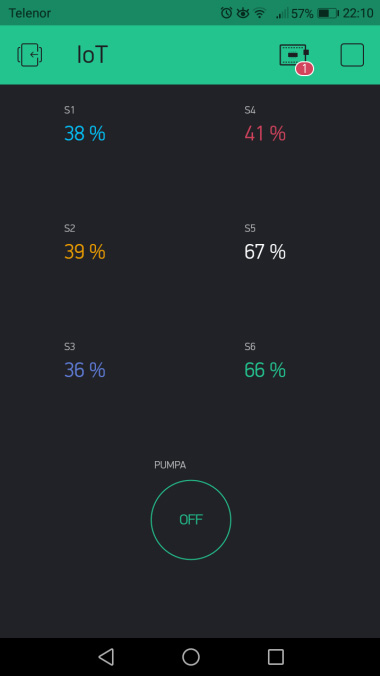
And here is how Blynk’s (on our phone) side looks like:
Source Code For Arduino UNO :
/*
    Written by Pavle Glušac
        @pavleglusac
                            */
#include <SoftwareSerial.h>
SoftwareSerial Arduino(8, 9); // Configuring a serial connection with NodeMCU using these pins (RX, TX)
int sens[6], i = 1, j;
String p, prim;
char primljen;
int relay = 7;
void setup() {
Serial.begin(115200); // Starting a serial connection for debugging and checking
Arduino.begin(9600); // Starting a serial connection with NodeMCU
pinMode(relay, OUTPUT);
pinMode(4, INPUT);
}
//Marker
void loop() {
// Reading sensor values and converting them to one string
sens[0] = analogRead(0);
sens[0] = map(sens[0], 0, 1023, 0, 100); // Converting them to 0-100% format
sens[1] = analogRead(1);
sens[1] = map(sens[1], 0, 1023, 0, 100);
sens[2] = analogRead(2);
sens[2] = map(sens[2], 0, 1023, 0, 100);
sens[3] = analogRead(3);
sens[3] = map(sens[3], 0, 1023, 0, 100);
sens[4] = analogRead(4);
sens[4] = map(sens[4], 0, 1023, 0, 100);
sens[5] = analogRead(5);
sens[5] = map(sens[5], 0, 1023, 0, 100);
// Converting them to one string
//I use string "p" for sending values
String p;
for(int j = 0; j <= 5; j++)
{
  if(sens[j] < 10)
  {
    p.concat("0");
    p.concat(String(sens[j]));
  }
  else if(sens[j] == 100)
  {
    p.concat("aa");
  }
  else p.concat(String(sens[j]));
}

Arduino.println(p); // Sending them to NodeMCU
delay(500);
Arduino.flush(); // Waits for transmission to be over

i = digitalRead(4); // Checking if the relay should be on or off
if(i == 0)digitalWrite(relay, LOW);
if(i == 1)digitalWrite(relay, HIGH);
Serial.println(i); // Used for debugging
delay(1000);
}
Source Code For NodeMCU’s ESP866 :
/**
      Written by Pavle Glušac
            @pavleglusac
                              ***/
#define BLYNK_PRINT Serial
#include <ESP8266WiFi.h>
#include <BlynkSimpleEsp8266.h>
#include <SoftwareSerial.h>
SoftwareSerial NodeMCU(D2, D3); // Configuring a serial connection with these pins (RX, TX)
char auth[] = ""; // Insert your own Blynk authentication token
String content; // Variable that gets serial data
char ssid[] = ""; // Insert your own WiFi ssid
char pass[] = ""; // Insert your own WiFi password
BlynkTimer timer; // Creating a timer object

void sendValues()
{
  char c;
  content = NodeMCU.readString(); // Reading serial data
  Serial.println(content); // I used this line to check if data is correct
  // This is where I process the data
  /* In Arduino code, you can see that data is sent as one string
  which contains every value so we get those values for each sensor
  like this */
  String v1 = content.substring(0, 2);
  String v2 = content.substring(2, 4);
  String v3 = content.substring(4, 6);
  String v4 = content.substring(6, 8);
  String v5 = content.substring(8, 10);
  String v6 = content.substring(10, 12);
  if(v1 == "aa")v1 = "100";
  if(v2 == "aa")v1 = "100";
  if(v3 == "aa")v1 = "100";
  if(v4 == "aa")v1 = "100";
  if(v5 == "aa")v1 = "100";
  if(v6 == "aa")v1 = "100";
  // Making it prettier
  String str1 = v1 + " %";
  String str2 = v2 + " %";
  String str3 = v3 + " %";
  String str4 = v4 +  " %";
  String str5 = v5 + " %";
  String str6 = v6 + " %";
  // Sending processed data to server and writing them to virtual pins
  Blynk.virtualWrite(V0, str1);
  Blynk.virtualWrite(V1, str2);
  Blynk.virtualWrite(V2, str3);
  Blynk.virtualWrite(V3, str4);
  Blynk.virtualWrite(V4, str5);
  Blynk.virtualWrite(V5, str6);
}
// Marker

void setup()
{
  Serial.begin(19200); // Starting serial connection for debugging and checking
  Blynk.begin(auth, ssid, pass); // Starting a connection with Blynk's server
  delay(500); // Adding a little delay so that we can connect properly
  timer.setInterval(1000L, sendValues); // Timer will start the "sendValues" function every second
  NodeMCU.begin(9600); // Starting a serial communication with Arduino
  pinMode(D2,INPUT); // Pin used as recieve (RX) pin
  pinMode(D3,OUTPUT); // Pin used as transmit (TX) pin
}

void loop()
{
  Blynk.run(); //Initiates Blynk
  timer.run(); //Initiates Timer
}
Here are pictures of the entire project:
Watch Video :
Project Copyrights ©PavleGlušac
2 comments
great project.
thanks
Hello friends. Is there anyone in Israel who is also interested in this project. I would like to receive a link / email of friends from Israel. Thank you
Comments are closed.
Add Comment