INTRODUCTION:
Nowadays ROBOTS are very useful because of their high-level performance and reliability and which is a great help for human beings, and even many industries use robots. In today’s world ROBOTICS are fast growing and interesting field so we decide to work on the robotic project and make something which will make human life simple in today’s world.
This project is based on Arduino microcontroller, This robotic vehicle has the following feature:
- Obstacle avoidance
This robot consists of built-in intelligence to cover an area around it. It uses ultrasonic sensors (i.e work on the principle of sound waves) which are used to sense the obstacle coming in the path of the robot. The robot will sense the obstacle and move in a particular direction and be avoiding the obstacle which is coming in its path.
DESIGN OF PROJECT:
This diagram consists of following main blocks:
- Ultrasonic sensors (HC-SR04).
- Arduino UNO.
- Motor driver (L298N).
- DC motors.
OVERVIEW OF EACH BLOCK:
- ULTRASONIC SENSOR (HC-SR04):
Ultrasonic sensor module provides 2cm – 400cm non-contact measurement function. The module include an ultrasonic transmitter and receiver and control circuit. The basic principle of work:
- Using IO trigger of an at least 10us high signal.
- The module sends automatically eight 40KHz pulses and detects whether there is a pulse signal back.
- If the signal back, through high level, time of high output IO duration is the time from sending ultrasonic to returning.
WORKING PRINCIPLE OF ULTRASONIC SENSOR:
1) ARDUINO UNO:
This is the most important block of the whole system. Arduino UNO is basically a microcontroller and it is the decision making a logical device which has its own I/O ports, CPU embedded on a single chip.
2) Motor driver (L293D):
L298n is a driver IC which is used to drive left and right motors of the ROBOT. It is H-Bridge DC Motor controller, for controlling the rotation direction, we just need to inverse the direction of the current flow through the motor, and the most common method of doing that is by using an H-Bridge. An H-Bridge circuit contains four switching elements, transistors or MOSFETs, with the motor at the center forming an H-like configuration. By activating two particular switches at the same time we can change the direction of the current flow, thus change the rotation direction of the motor.
COMPONENTS USED:
- Ultrasonic sensors (HC-SR04).———————- (3)
- Motor driver (L293D).———————————–(1)
- Arduino UNO.———————————————(1)
- DC Motor (200 RPM)———————————– (4)
- 7.4V Rechargeablebattery.————————— (2)
- Jumper wires.
- Chassis plate
Schematic Diagram:
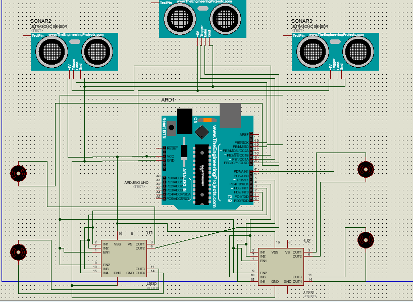
Source CODE:
/*  OBSTACLE AVOIDANCE ROBOT */
int echoPinRight = 6;         // PIN 6 TO RECEIVE ECHO FROM RIGHT SENSOR
int trigerPinRight = 7;       // PIN 7 TO TRIGER THE RIGHT SENSOR
int echoPinMiddle = 8;        // PIN 8 TO RECEIVE ECHO FROM MIDDLE SENSOR
int trigerPinMiddle = 9;      // PIN 9 TO TRIGER THE MIDDLE SENSOR
int echoPinLeft = 13;         // PIN 13 TO RECEIVE ECHO FROM LEFT SENSOR
int trigerPinLeft = 10;       // PIN 10 TO TRIGER THE LEFT SENSOR
int motorA1 = 2;              // PIN 2 FOR CONTROLLING MOTOR A1
int motorA2 = 3;              // PIN 3 FOR CONTROLLING MOTOR A2
int motorB1 = 4;              // PIN 4 FOR CONTROLLING MOTOR B1
int motorB2 = 5;              // PIN 4 FOR CONTROLLING MOTOR B1
int motorSpeed = 11;          // ARDUINO PWM PIN 11 TO CONTROL MOTORS SPEED
double echoValueright, echoValuemiddle, echoValueleft;
// INITIALIZING VARIABLE TO RECEIVE ECHO FROM THE SENSORS
float cmRight, cmMiddle, cmLeft;
 // INITIALIZING VARIABLES TO STORE DISTANCE MEASURED OF SENSORS IN CENTIMETERS
void setup()
{
  Serial.begin(9600);                                     // STARTING SERIAL COMMUNICATION TO PRINT VALUES RECEIVED BY SENSOR ON SERIAL MONITER
  pinMode(echoPinLeft, INPUT);                           // SETTING ARDUINO PIN AS INPUT
  pinMode(trigerPinLeft, OUTPUT);                       // SETTING ARDUINO PIN AS OUTPUT
  pinMode(echoPinMiddle, INPUT);                        // SETTING ARDUINO PIN AS INPUT
  pinMode(trigerPinMiddle, OUTPUT);                    // SETTING ARDUINO PIN AS OUTPU
  pinMode(echoPinRight, INPUT);                        // SETTING ARDUINO PIN AS INPUT
  pinMode(trigerPinRight, OUTPUT);                     // SETTING ARDUINO PIN AS OUTPU
  pinMode(motorSpeed, OUTPUT);          // SETTING ARDUINO PIN AS OUTPUT TO CONTROL MOTOR SPEED
}
void loop()
{
  float cmR, cmM, cmL;                                      // INITIALIZING VARIABLES TO STORE DISTANCE OBTAINED FROM SENSORS IN CM
  int maxRange = 30;                                        // SETTING MAX RANGE
  analogWrite(motorSpeed, 90);                              // SETTING MOTORS SPEED YOU CAN SET SPEED BETWEEN 0-255
  digitalWrite(motorA1, HIGH);
  digitalWrite(motorA2, LOW);
  digitalWrite(motorB1, HIGH);
  digitalWrite(motorB2, LOW);


  cmR = sensorRight();
  cmM = sensorMiddle();
  cmL = sensorLeft();
  Serial.println();
  Serial.print(cmL);
  Serial.print("        ");
  Serial.print(cmM);
  Serial.print("        ");
  Serial.print(cmR);
  if (cmR < maxRange)
  {
    digitalWrite(motorA1, LOW);
    digitalWrite(motorA2, HIGH);
    digitalWrite(motorB1, HIGH);
    digitalWrite(motorB2, LOW);
  }
  if (cmL < maxRange)
  {
    digitalWrite(motorA1, HIGH);
    digitalWrite(motorA2, LOW);
    digitalWrite(motorB1, LOW);
    digitalWrite(motorB2, HIGH);
  }

  if (cmM < maxRange) { if (cmL > cmR)
    {
      digitalWrite(motorA1, LOW);
      digitalWrite(motorA2, HIGH);
      digitalWrite(motorB1, HIGH);
      digitalWrite(motorB2, LOW);
    }
    else if (cmR > cmL)
    {
      digitalWrite(motorA1, HIGH);
      digitalWrite(motorA2, LOW);
      digitalWrite(motorB1, LOW);
      digitalWrite(motorB2, HIGH);
    }
    else if (cmR < maxRange && cmL < maxRange)
    {
      digitalWrite(motorA1, LOW);
      digitalWrite(motorA2, HIGH);
      digitalWrite(motorB1, LOW);
      digitalWrite(motorB2, HIGH);
    }
  }

  delay(500);
}
float sensorRight()               // FUUNCTION TO OPERATE RIGHT SENSOR
{
  digitalWrite(trigerPinRight, LOW);
  delayMicroseconds(2);
  digitalWrite(trigerPinRight, HIGH);
  delayMicroseconds(10);
  digitalWrite(trigerPinRight, LOW);
  echoValueright = pulseIn(echoPinRight, HIGH);
  cmRight = echoValueright / 59;
  //inchesRight=cmRight/2.54;
  //Serial.print(cmRight);
  return (cmRight);
}
float snssorMiddle()              // FUNCTION TO OPERATE MIDDLE SENSOR
{
  digitalWrite(trigerPinMiddle, LOW);
  delayMicroseconds(2);
  digitalWrite(trigerPinMiddle, HIGH);
  delayMicroseconds(10);
  digitalWrite(trigerPinMiddle, LOW);
  echoValuemiddle = pulseIn(echoPinMiddle, HIGH);
  cmMiddle = echoValuemiddle / 59;

  //inchesMiddle=cmMiddle/2.54;
  //Serial.print(cmMiddle);
  return (cmMiddle);
}
float sensorLeft()              // FUNCTION TO OPERATE LETT SENSOR
{
  digitalWrite(trigerPinLeft, LOW);
  delayMicroseconds(2);
  digitalWrite(trigerPinLeft, HIGH);
  delayMicroseconds(10);
  digitalWrite(trigerPinLeft, LOW);
  echoValueleft = pulseIn(echoPinLeft, HIGH);
  cmLeft = echoValueleft / 59;
  //inchesLeft=cmLeft/2.54;
  //Serial.print(cmLeft);
  return (cmLeft);
}
SOFTWARE :
- ARDUINO IDE:
Arduino IDE is a software used to program ARDUINO microcontroller and is easy to use.
APPLICATIONS:
- It can be used as services ROBOT, for the purpose of household work and other indoor applications.
- This concept can be modified in an automatic car parking system,
FUTURE IMPROVEMENTS AND SCOPE:
- By adding a camera (i.e webcam) it can be used as surveillance ROBOT.
- By adding a temperature sensor, water tank and some changes in programming, it can be used as autonomous for firefighting ROBOT.
Watch Video:
3 comments
Hello Mr Ahsan, could you send me the soft copy of this report project to my email. noorthuwaibah97@gmail.com thank you very much
motor driver used is L298N or L293D
Hello air could u plzz send me the code and the module file and the report plzz urgent email abhishek123723@gmail.com
Comments are closed.
Add Comment